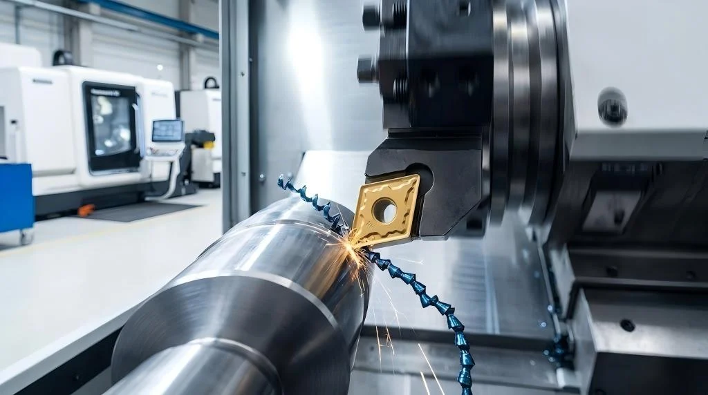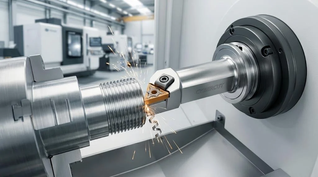
In the high-stakes environment of CNC turning, no operation induces more anxiety for machinists and production engineers than the final parting-off cycle. Unlike standard OD (Outer Diameter) turning, where the tool is robustly supported and chips flow freely away from the cutting zone, grooving and parting are inherently constrained operations. The cutting edge is buried deep within the workpiece, surrounded on three sides by solid metal. If chip evacuation fails or the tool deflects, the insert will shatter. Because parting off is typically the final operation in the machining cycle, a catastrophic failure at this stage scraps a nearly completed, high-value component, devastating your production economics.
To eliminate these bottlenecks and secure a highly reliable, lights-out manufacturing process, facilities must move beyond generic turning inserts and invest in engineered grooving and parting tools. This definitive engineering guide will dissect the physics of plunge cutting, the metallurgical requirements of parting substrates, and the advanced programming strategies required to maximize efficiency, extend tool life, and achieve flawless surface finishes.
The Challenges of Deep Grooving and How to Overcome Them

Deep grooving presents a unique set of physical and tribological challenges that differentiate it entirely from conventional turning or facing operations. When a standard turning tool engages the material, the cutting forces are primarily tangential and axial. In contrast, grooving and parting tools are subjected to severe radial forces as they plunge toward the spindle’s centerline.
1. The Confined Cutting Zone and Chip Evacuation
The most significant hurdle in deep grooving is the lack of physical space. As the insert plunges deeper, the groove’s walls create a restrictive channel. If the chip generated is wider than the groove itself, it will severely score the sidewalls, resulting in a rejected surface finish. Worse, if the chip fails to curl and exit the channel, it will pack into the bottom of the groove. The tool will then recut these work-hardened chips, leading to an instantaneous spike in cutting pressure and catastrophic insert failure.
To overcome this, modern high-performance grooving inserts feature complex geometries that physically compress the chip’s width. By utilizing a “V” or “U” shaped chipbreaker on the rake face, the insert forces the chip to fold in on itself and curl into an easily evacuated “clock spring” shape.
2. Tool Overhang and Radial Deflection
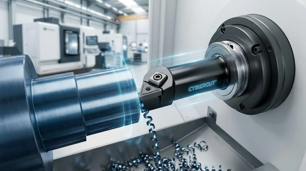
To part off a solid 50mm diameter bar, the tool must reach at least 25mm deep. This requires a long tool overhang, which exponentially decreases structural rigidity. A lack of rigidity leads directly to low-frequency vibration (chatter) and poor dimensional accuracy. The engineering solution relies on specialized tool holder design. Utilizing a reinforced blade-style holder clamped in a robust block provides superior vertical rigidity. Furthermore, maintaining the absolute minimum overhang required for the specific bar diameter is a non-negotiable rule when setting up your precision grooving and parting tools.
Selecting the Right Insert Width and Grade for Parting Off
Selecting the correct insert is a delicate balancing act between material savings, structural stability, and the physical limitations of the machine tool.
Determining the Optimal Insert Width
The width of the parting insert dictates the amount of raw material turned into swarf per cycle. In high-volume production of expensive alloys, minimizing insert width saves thousands of dollars. However, an insert that is too narrow lacks the structural integrity to plunge deeply without wandering (deflecting laterally). As a rule of thumb, choose the narrowest insert capable of reaching the center of the bar without exceeding a depth-to-width ratio of 8:1.
Insert Handedness and Lead Angles
When a neutral insert parts off a solid bar, the sudden release leaves a small protrusion known as a “pip”. For components requiring a perfectly flat face, machinists utilize handed inserts with a lead angle (typically 5° to 15°). This cleanly shears the pip off. However, the angled cutting edge introduces lateral cutting forces, pushing the tool sideways. When utilizing handed advanced parting inserts, you must reduce your feed rate by 20% to 30% to compensate for this lateral pressure.
Carbide Substrate and Coating Selection
Because cutting speed drops to absolute zero exactly at the centerline, the insert transitions from shearing the metal to extruding it. This requires a carbide substrate with exceptional toughness (high cobalt content). PVD coatings are heavily favored over CVD coatings for grooving and parting tools because PVD allows for a much sharper cutting edge, significantly reducing built-up edge (BUE) at low surface speeds.
[Table] Troubleshooting Common Grooving Tool Failures
Even with premium tooling, parameters must be perfectly dialed in. Use this diagnostic table to troubleshoot common failures.
| Failure Mode | Visual Evidence | Primary Causes | Engineering Solutions |
| Vibration (Chatter) | High-pitched squeal; heavy ripple marks on groove. | Tool overhang too long; center height incorrect; feed too low. | 1. Shorten blade overhang. 2. Verify center height. 3. Increase feed rate. |
| Insert Breakage | Total destruction of the cutting edge and holder. | Chip packing; interrupted cut shock; cutting past center. | 1. Implement peck-grooving. 2. Increase coolant pressure. 3. Stop feed 0.5mm before center. |
| Rapid Flank Wear | Excessive abrasion on the clearance face. | Cutting speed too high; carbide grade too tough/soft. | 1. Reduce RPM. 2. Upgrade to a harder grade from your grooving tool supplier. |
| Poor Chip Control | Long, stringy chips wrapping around the workpiece. | Feed rate too low; incorrect chipbreaker geometry. | 1. Increase feed rate. 2. Select tighter chip groove geometry. |
| Concave/Convex Face | Parted-off face is dished or domed. | Insert lead angle causing lateral deflection; feed too high. | 1. Switch to neutral insert. 2. Reduce feed by 30%. 3. Ensure holder is perpendicular. |
The Importance of High-Pressure Coolant in Grooving
In standard turning, flood coolant cascades over the workpiece. In deep grooving, the rapidly spinning workpiece acts like a centrifugal pump, throwing standard flood coolant away from the cutting zone. By the time the insert reaches a depth of 10mm, the cutting edge is virtually dry, leading to severe thermal expansion and rapid tool degradation.
Upgrading your setup to utilize internal, high-pressure coolant (HPC) is the single most effective way to maximize the performance of your grooving and parting tools. Modern tool blocks deliver a focused jet of coolant directly exactly at the shear zone.
The Threefold Benefit of HPC: 1) Thermal Shock Prevention: Maintains a consistent temperature. 2) Hydraulic Chip Breaking: The kinetic energy forces chips to snap. 3) Lubricity at the Centerline: Drastically reduces friction. Explore coolant-through grooving holders to instantly upgrade your process reliability.
Strategies for Effective Chip Control in Deep Cuts
Relying solely on the insert’s geometry is often insufficient when cutting extremely gummy materials. Manufacturing engineers must employ advanced CNC programming strategies.
1. Peck Grooving (The Woodpecker Cycle)
Instead of a single continuous plunge, the CNC is programmed to plunge 2mm to 3mm, retract 0.5mm to break the chip, and plunge again. This guarantees that chips never exceed a manageable length, eliminating the risk of swarf packing.
2. The “Plunge and Turn” Strategy (Widening the Groove)
When a wide groove is required, utilizing a single wide insert generates massive radial pressure and chatter. The superior strategy is to use a narrower insert from your specialized grooving and parting tools arsenal. The programmer commands multiple plunging passes to rough out the width, followed by a lateral turning pass along the floor. Highly advanced inserts feature a “twisted” geometry allowing them to seamlessly transition from plunging to axial turning.
3. Modulating Feed at the Centerline
When parting off, to prevent the component from tearing off prematurely and to protect the delicate corner, the feed rate must be reduced by 50% to 75% when the tool is approximately 2mm away from the centerline. This ensures a clean shear and prolongs tool life.
Frequently Asked Questions (FAQ)
Q1: Why is exact center height so critical for grooving and parting tools?
A: Parting inserts have minimal front clearance. If the tool is above center, the flank rubs against the workpiece, causing friction and chatter. If below center, the insert grabs the material and snaps the blade.
Q2: Can I use the same insert for both grooving and parting off?
A: While possible, it is not optimal. Grooving inserts are optimized for floor finish and corner radii during lateral turning. Parting inserts are highly specialized strictly for deep radial plunging and efficient chip narrowing.
Q3: What causes the “pip” in the center of a parted-off component?
A: The pip occurs because the remaining material connection becomes too weak to withstand cutting forces, breaking off before cleanly cut. A 15-degree lead angle and reduced feed rate near the center minimizes this.
Q4: Why does my parting blade keep drifting to the side, making a concave cut?
A: Blade drift is caused by using a handed (angled) insert with too aggressive of a feed rate, pushing the blade laterally, or a holder not perfectly perpendicular to the spindle axis.
Q5: How do I choose between a blade-style holder and a solid integral shank holder?
A: Solid integral shank holders are extremely rigid but limited in depth. Blade-style holders are modular, providing adjustable overhang for maximum rigidity in deep cuts while allowing easy blade replacement after a crash.
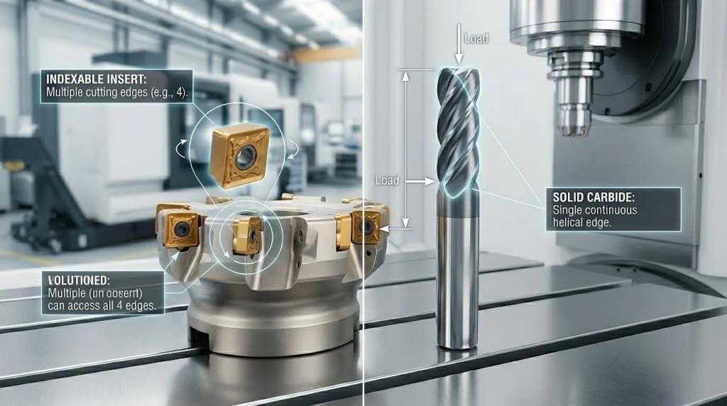
Q6: What is the benefit of a single-ended vs. double-ended grooving insert?
A: Double-ended inserts offer economy but limit max depth of cut because the rear edge obstructs the groove. Single-ended inserts from high-end grooving and parting tools collections have no rear obstruction, allowing for infinitely deeper cuts.