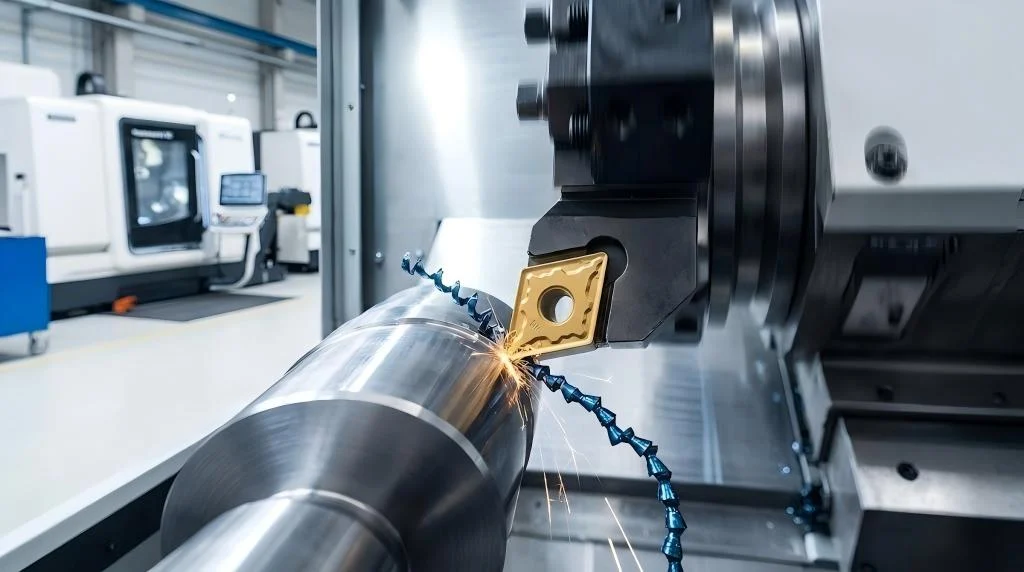
In the highly competitive landscape of industrial manufacturing, achieving uncompromising precision and maximum throughput is non-negotiable. Whether you are operating a high-volume automotive parts production line or a specialized aerospace component facility, the efficiency of your lathe operations fundamentally dictates your profitability. At the very heart of this machining ecosystem lies a critical component: the cutting tool. Understanding the complex engineering principles required to select the optimal CNC turning inserts for steel machining is the defining factor between a highly optimized workflow and one plagued by excessive tool wear, machine downtime, and rejected parts.
Steel, classified universally under the ISO P material group, is the most frequently machined metal globally. However, treating “steel” as a single, uniform material is a critical engineering mistake. The spectrum ranges from low-carbon, highly ductile “gummy” steels that cling to the cutting edge, to high-tensile alloyed steels that subject tools to immense thermal and mechanical stress. Using generic tooling leads to suboptimal material removal rates (MRR) and catastrophic tool failure. This comprehensive guide systematically dismantles the complexities of selecting the ultimate CNC turning inserts, exploring the metallurgical science of carbide, the thermodynamics of advanced coatings, intricate edge geometries, and the physics of tool wear.
The Material Science of CNC Turning Inserts: The Carbide Substrate

Before discussing shape or size, we must examine the microscopic foundation of indexable tooling. Modern CNC turning inserts are predominantly manufactured from cemented carbide, a remarkable composite material engineered through powder metallurgy.
The Tungsten Carbide (WC) and Cobalt (Co) Matrix
The core substrate consists of hard Tungsten Carbide (WC) particles held together by a softer, metallic Cobalt (Co) binder. The ratio of these two elements, alongside the grain size of the tungsten carbide, dictates the mechanical properties of the tool:
- High Hardness (Low Cobalt Content / Sub-Micron Grain Size): By reducing the cobalt binder and utilizing ultra-fine tungsten carbide grains, manufacturers create an insert with extreme hardness and resistance to plastic deformation. These substrates excel in continuous, high-speed turning of unalloyed steels where constant, immense heat is generated. However, the trade-off is higher brittleness.
- High Toughness (High Cobalt Content / Coarse Grain Size): Increasing the cobalt ratio provides the substrate with microscopic elasticity. These inserts can absorb severe mechanical shocks, making them the mandatory choice for heavy roughing operations, interrupted cuts (such as turning hexagonal bar stock or cross-drilled shafts), and operations running on older, less rigid machinery.
When you browse our comprehensive selection of turning tools, understanding this balance between hardness (wear resistance) and toughness (shock resistance) is your first step toward true process optimization.
Decoding ISO P Classifications for Steel Turning


The ISO classification system is the global language of cutting tools. Steel falls strictly into the ISO P category, visually identified by the color blue. Within the ISO P category, carbide grades are further subdivided by numbers, typically ranging from P01 to P50. This numerical scale is highly logical and directly reflects the hardness-to-toughness ratio discussed above.
- P01 to P10 Grades: These are the hardest, most wear-resistant grades available for steel. They are designed exclusively for high-speed, continuous finishing operations where minimal material is removed, but surface finish requirements are exceptionally tight. They cannot withstand vibration or interrupted cutting.
- P20 to P30 Grades: These represent the “universal” sweet spot for most machine shops. They offer a highly balanced formulation, providing excellent wear resistance for continuous turning while possessing enough structural integrity to handle moderate interruptions and variations in depth of cut.
- P40 to P50 Grades: These are the toughest grades in the ISO P spectrum. They operate at much lower cutting speeds but can survive brutal, heavy roughing, extreme interrupted cuts, and the forging scales often found on raw steel blanks.
Advanced Tribology: CVD vs. PVD Coatings in Steel Turning
The extreme tribological conditions (friction, wear, and lubrication) present at the cutting edge during steel machining generate localized temperatures exceeding 1000°C. Raw carbide would rapidly dissolve under these conditions. To protect the substrate, CNC turning inserts are subjected to advanced deposition technologies to create microscopic, ultra-hard ceramic layers.
Chemical Vapor Deposition (CVD)
CVD is the undisputed champion for general turning and heavy roughing of ISO P steels. The coating process occurs at extremely high temperatures (around 1000°C), allowing for relatively thick, multi-layered coatings (typically 10 to 20 microns). A high-performance CVD insert from a specialized turning inserts catalog usually features three distinct functional layers:
- Titanium Carbonitride (TiCN): The innermost layer bonded directly to the carbide substrate. It provides massive resistance to abrasive flank wear.
- Aluminum Oxide (Al2O3): The critical middle layer. It acts as an impenetrable thermal shield, preventing the massive heat of the shear zone from transferring into the carbide substrate, thereby preventing plastic deformation at high speeds.
- Titanium Nitride (TiN): The distinctive gold-colored top layer. It lowers the coefficient of friction, reducing built-up edge, and serves as an excellent visual wear indicator for the operator.
Physical Vapor Deposition (PVD)
PVD coatings are applied at much lower temperatures (around 500°C). This low-temperature process prevents the carbide substrate from becoming brittle, allowing the insert to maintain incredibly sharp cutting edges. The coatings are thin (usually 2 to 5 microns) and incredibly smooth. While they lack the extreme thermal barrier of CVD’s Al2O3 layer, PVD-coated CNC turning inserts are superior for finishing operations, turning sticky low-carbon steels, thread turning, and parting off, where maintaining a razor-sharp edge is more critical than thermal shielding.
Mastering Insert Geometries: Shapes, Rake Angles, and Chip Control
Tool geometry dictates how efficiently the insert shears the metal and manages the resulting swarf (chips). Selecting the correct geometry involves analyzing the basic shape, the clearance angle, and the topography of the chipbreaker.
Positive vs. Negative Inserts
- Negative Inserts: Feature a 0-degree clearance angle. They are robust, double-sided, and direct cutting forces axially into the tool holder, making them exceptionally rigid. They are the standard for heavy roughing.
- Positive Inserts: Feature a built-in clearance angle (e.g., 7° or 11°). They are single-sided but present a much sharper cutting wedge to the material. They generate significantly lower cutting forces, making them the required choice for internal boring, turning slender, unstable shafts, or finishing operations.
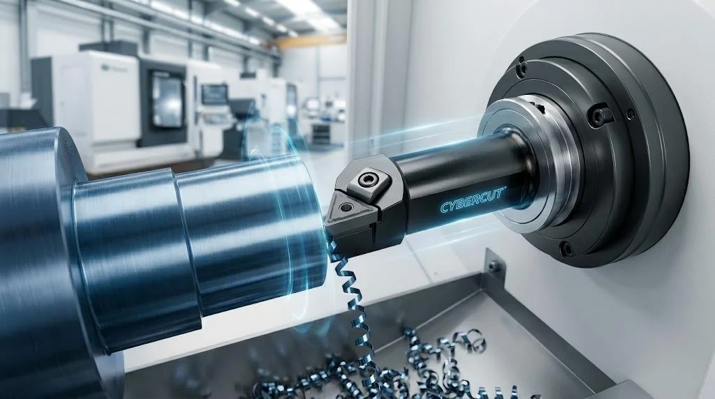
The Physics of Chipbreakers
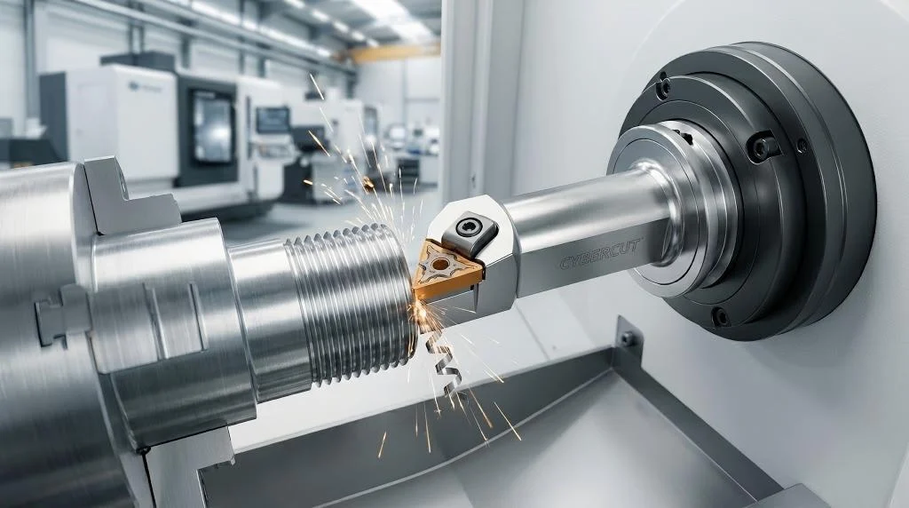
Steel, by nature, produces long, continuous, and hazardous chips if not properly managed. The chipbreaker is a highly engineered 3D groove on the rake face of the insert designed to force the chip to curl tightly and snap into manageable, “comma-shaped” fragments.
- Roughing Geometries: Feature wide, open grooves. They are designed to withstand massive feed rates and deep cuts without clogging.
- Finishing Geometries: Feature tight, narrow grooves positioned very close to the cutting edge to aggressively curl the incredibly thin chips generated during fine finishing passes. To find the exact geometry for your needs, explore high-performance CNC turning insertscategorized by application.
[Table] CNC Turning Insert Shapes: The Ultimate ISO Nomenclature Guide
| ISO Letter | Shape | Point Angle | Structural Strength | Primary Industrial Application |
| S | Square | 90° | Maximum | Heavy roughing, face turning, chamfering. Most economical. |
| C | Rhombic | 80° | High | The industry standard for general turning and facing. |
| W | Trigon | 80° | High | General turning. Replaces C shapes due to offering 6 edges. |
| T | Triangle | 60° | Medium | Light roughing to medium finishing. |
| D | Rhombic | 55° | Low | Profiling and undercutting. High accessibility. |
| V | Rhombic | 35° | Minimum | Intricate profiling, deep spherical undercuts. Requires extreme care. |
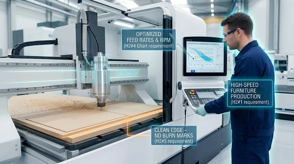
Calculating the Physics of Cutting: Speeds, Feeds, and Depth of Cut
To maximize the ROI of your premium CNC turning inserts, operators must move away from “guesstimating” parameters and apply mathematical formulas.
- Cutting Speed (vc) and Spindle Speed (n):
Cutting speed (measured in m/min) dictates the thermal generation at the shear zone. To translate the manufacturer’s recommended cutting speed into a usable machine parameter (RPM), use the formula: n = (vc * 1000) / (π * Dc)
- Feed Rate (fn) and Surface Finish (Ra):
The feed rate (mm/rev) directly impacts the theoretical surface finish. The finish is a geometric relationship between the feed rate and the tool’s nose radius. To estimate the surface finish, engineers use the formula: Ra ≈ (f^2 / (8 * r)) * 1000
Troubleshooting Common Wear Mechanisms in CNC Turning Inserts
Even the best tools wear out. However, the type of wear tells a diagnostic story about your machining parameters. By learning to “read” your inserts, you can dramatically optimize your process.
- Flank Wear (Normal Wear): The ideal wear mechanism. Appears as even abrasion along the clearance face. Index the insert when wear reaches ~0.3 mm.
- Crater Wear: Occurs on the top rake face due to chemical diffusion and extreme heat. Solution: Lower cutting speed or switch to a thicker CVD aluminum oxide coated grade.
- Built-Up Edge (BUE): The workpiece material pressure-welds itself to the cutting edge, ruining surface finish. Solution: BUE is caused by low temperatures. Increase cutting speed (vc) or switch to a PVD-coated insert.
- Plastic Deformation: The cutting edge melts and droops downward due to thermal overload. Solution: Reduce cutting speed and feed rate, or select a harder carbide grade.
- Notch Wear (Depth of Cut Line Wear): Localized wear where the insert intersects the outer diameter of the workpiece. Solution: Vary your depth of cut across multiple passes.
If you are consistently experiencing abnormal wear patterns, it is time to evaluate your tooling strategy and upgrade your turning operations here.
Frequently Asked Questions (FAQ)
Q1: How do I choose the correct nose radius for my CNC turning inserts?
A: The nose radius dictates edge strength and surface finish. For heavy roughing, choose a large radius (1.2mm/1.6mm). For finishing, choose a smaller radius (0.4mm/0.2mm) to minimize radial cutting forces and prevent vibration.
Q2: Why does my insert keep breaking during interrupted cuts?
A: Breakage is caused by mechanical and thermal shock. Switch to a tougher carbide grade (higher cobalt), a stronger shape (Square/Round), and turn off liquid coolant to prevent thermal cracking.
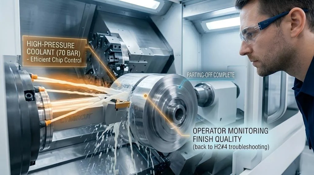
Q3: Is high-pressure coolant necessary for turning steel?
A: While flood coolant works for basics, high-pressure coolant (70 bar/1000 PSI+) forcibly breaks chips, acts as a thermal wedge, and significantly extends tool life in difficult alloyed steels.
Q4: What is the difference between an M tolerance and a G tolerance insert?
A: M tolerance inserts are molded and sintered, making them economical for roughing. G tolerance inserts are fully precision ground on all peripheries, providing absolute repeatability required for high-precision finishing.
Q5: Can I turn hardened steel (over 45 HRC) with standard ISO P carbide inserts?
A: No, standard ISO P inserts will fail. You must switch to PCBN (Polycrystalline Cubic Boron Nitride) inserts or specialized ultra-hard carbide grades with heavy-duty PVD coatings for hard part turning.
Q6: How do I fix poor surface finish when turning mild steel?
A: Poor finish on mild steel is usually BUE or poor chip breaking. Increase your cutting speed, increase feed slightly to engage the chipbreaker, and ensure continuous high-quality coolant flow. To find the exact finishing geometries required, find the right CNC turning inserts tailored for low-carbon applications.