Introduction: The Hidden Cost of Premature Failure

In the economics of CNC machining, the cost of a carbide insert is often the smallest variable. The real cost lies in machine downtime. Every time an operator stops the spindle to index a worn insert, you lose 5-10 minutes of production time. If that insert fails unpredictably (catastrophic breakage), you may also lose the workpiece and damage the tool holder. Therefore, the goal is not just to make the tool last longer, but to make it last predictably.
Many shops accept short tool life as ‘part of the job’ when machining stainless steel or superalloys. This is a fallacy. Premature wear is almost always a symptom of incorrect application physics. Whether you are turning, milling, or grooving, the principles of heat management and rigidity remain constant.
Drawing from Premitools’ experience in supplying industrial CNC cutting tools, we present 5 engineering-backed strategies to maximize your cost-per-edge performance.
Strategy 1: Respect the “Speed vs. Heat” Equation
The most common cause of rapid wear is simply running too fast. According to Taylor’s Tool Life Equation, a 20% increase in cutting speed (Vc) can reduce tool life by 50%.
The Efficiency Zone
Machinists often increase RPM to shorten cycle time. However, carbide has a thermal limit. Once the cutting temperature exceeds the coating’s oxidation point (e.g., 800°C for TiCN), the coating fails, and the substrate degrades rapidly.
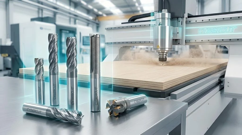
Instead of pushing Vc (Speed), try pushing Fn (Feed Rate). Increasing the feed rate increases cutting forces but has a much smaller impact on heat. This allows you to remove material faster without burning up the insert. This strategy is central to our high-performance milling tools.
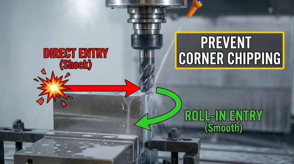
Strategy 2: Rigidity is the Enemy of Vibration
Carbide is extremely hard (1600+ Vickers), which means it is also brittle. It cannot tolerate tensile stress caused by vibration (chatter).
Overhang Rules
Micro-chipping along the cutting edge is often misdiagnosed as ‘wear’. It is actually impact damage from vibration. Ensure your tool holder overhang is kept to a minimum (ideally < 3x Diameter). If deep reach is required, use carbide-shank boring bars or heavy-metal shanks, especially for internal threading.
Clamping Maintenance
Check the insert seat. If the shim or pocket is damaged/dented, the insert will not sit flat. A gap of just 0.02mm can allow the insert to flex and snap under load.
Strategy 3: The “Thermal Shock” Paradox in Milling
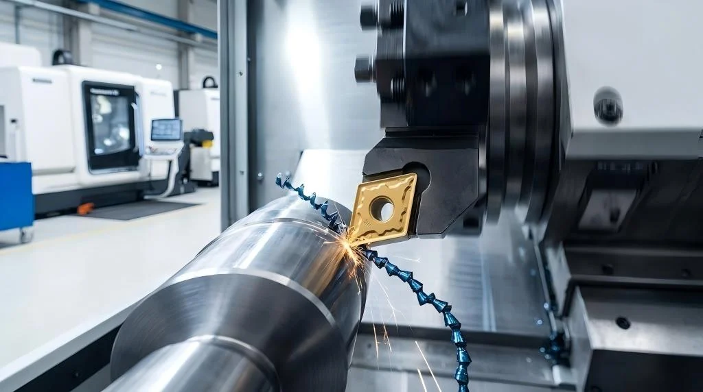
In turning operations, the tool is in constant contact with the metal, heating up steadily. In milling, the tool enters and exits the cut continuously (interrupted cut).
To Cool or Not to Cool?
If you use coolant in milling steel, the insert edge heats up to 700°C in the cut and is instantly quenched to 20°C by the coolant upon exit. This rapid cycling (Thermal Shock) causes Comb Cracks perpendicular to the cutting edge. Eventually, the edge crumbles.
The Fix: For milling steel and cast iron, Turn the Coolant OFF. Run dry with air blast. The coating is designed to handle the heat. Only use coolant for drilling, aluminum, or superalloys where heat adhesion is the primary failure mode.
Strategy 4: Forensic Analysis of Wear Patterns
You cannot fix what you cannot identify. Don’t just throw a worn insert in the bin; examine it with a 10x loupe. The wear pattern tells you what to change. This applies equally to grooving inserts.
1. Flank Wear (Normal)
Uniform abrasion on the side of the insert. This is the desired failure mode. It is predictable.
2. Crater Wear (Heat)
A depression on the top (rake face) of the insert. Caused by chemical reaction between the chip and carbide due to extreme heat.
Fix: Use a harder grade (more wear resistant) or reduce cutting speed.
3. Notch Wear (Work Hardening)
A deep gouge at the depth-of-cut line. Caused by the hardened skin of the material (common in Stainless Steel).
Fix:Vary the depth of cut (Ramping) or use a tougher grade.
Wear Pattern Analysis Matrix
| Wear Pattern | Visual Indicator | Root Cause & Corrective Action |
| Flank Wear | Even abrasion on side | Normal evolution. Index when VB = 0.3mm. |
| Crater Wear | Pit on top surface | Excess Heat. Reduce Speed or choose Al2O3 coating. |
| Plastic Deformation | Bulging/Melting tip | Overload. Reduce Feed or Depth of Cut. |
| Built-Up Edge (BUE) | Material welded to tip | Speed too low. Increase Vc or use PVD grade. |
| Chipping/Fracture | Random edge break | Vibration/Interruption. Check stability or use tougher grade. |
Strategy 5: Handling and Installation Hygiene
Carbide performance is often compromised before it even enters the machine.
No ‘Bin Dumping’
Never dump loose carbide inserts into a drawer. They will chip each other. Keep them in the original box until the moment of installation.
Torque Wrenches
Overtightening the insert screw causes stress fractures in the insert hole. Undertightening causes vibration. Use a factory-calibrated torque driver (typically 0.9Nm to 3.0Nm) to ensure consistent clamping force. This is standard practice for our high-precision PCD/CBN inserts.
FAQ: Optimizing Tool Life
1. When is the right time to index (rotate) the insert?
Do not wait for the edge to break. Standard industry practice is to index the insert when Flank Wear (VB) reaches 0.3mm for roughing, or 0.1mm – 0.2mm for finishing. Using it beyond this point drastically increases cutting forces and risks damaging the holder.
2. Speed vs. Feed: Which impacts tool life more?
Speed (RPM) kills tool life; Feed breaks the tool. If you need to extend life, reduce the Cutting Speed (Vc) by 10%. If you need to improve chip control, increase the Feed.
3. What do the coating colors mean?
- Gold (TiN): General purpose, good wear detection.
• Black/Grey (TiCN/Al2O3): High heat resistance for Cast Iron/Steel.
• Dark Violet/Blue (TiAlN): High performance for Stainless Steel and Superalloys.
Color helps identify the grade but rely on the spec sheet for application.
4. Can I reuse insert screws?
Insert screws stretch over time. It is recommended to replace the screw every 10th insert change. A $1 screw is cheaper than a wrecked $200 milling cutter body.
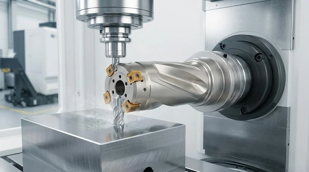
5. Why does my drill wear unevenly?
Uneven wear on a drill usually indicates Runout. Check your collet or hydraulic chuck. Runout greater than 0.02mm will overload one flute. Check our drilling tools for high-concentricity options.
6. Does ‘Thick’ coating mean longer life?
Not always. Thick CVD coatings offer great heat protection for turning steel but are brittle. Thin PVD coatings are tougher and sharper, making them better for stainless steel and milling. Thicker is not always better; application fit is key.
Conclusion: From Consumable to Asset
Extending carbide insert life is not about finding a ‘magic’ grade; it is about disciplined engineering. By optimizing your speeds, managing heat through correct coolant usage, and analyzing wear patterns to make data-driven corrections, you can significantly lower your manufacturing costs.
Premitools offers the technical support and premium grades you need to achieve this stability. Browse our complete tool catalog to start optimizing your shop today.