In the highly demanding sphere of industrial CNC machining, hole making is universally recognized as one of the most common yet structurally challenging operations. When a solid block of metal requires deep, large-diameter cavities, traditional manufacturing methods often dictate a multi-step, time-consuming process: spot drilling, pilot drilling with a smaller twist drill, and finally, enlarging the hole with a massive high-speed steel or solid carbide drill. This conventional methodology is fraught with inefficiencies, high tooling costs, and a constant risk of catastrophic tool failure deep within the workpiece.
To eliminate these bottlenecks, advanced manufacturing facilities have transitioned to a vastly superior engineering solution: indexable U drills. By leveraging the economic modularity of replaceable carbide inserts combined with highly engineered steel tool bodies, these tools have fundamentally rewritten the rules of material removal rates (MRR) in hole making. Whether you are running a high-horsepower vertical machining center (VMC) or a rigid CNC turning center, upgrading your setup with premium indexable U drills is the single most effective strategy to slash cycle times, consolidate tool stations, and drive down your cost-per-part. This definitive guide will explore the unique kinematics, insert metallurgy, and advanced operational strategies required to master these revolutionary drilling systems.
How Indexable U Drills Differ from Traditional Twist Drills

To understand the revolutionary nature of indexable U drills, we must first dissect the fundamental flaws of the traditional twist drill. A standard twist drill features a “chisel edge” at its very center. This chisel edge does not actually cut metal; it extrudes and pushes it aside. This requires immense axial thrust force from the machine spindle and inherently causes the drill to wander off-center upon initial contact, which is exactly why traditional drilling requires a pre-drilled pilot or spot hole.
The Elimination of the Chisel Edge
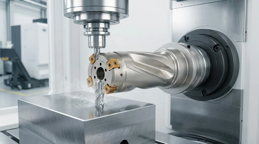
Indexable U drills completely eliminate the chisel edge. Instead of a solid point, the tool body is engineered with two independent, asymmetrical insert pockets: one positioned at the periphery (the outer insert) and one overlapping the centerline (the inner or central insert). Because the inner insert slightly crosses the absolute center of the tool’s rotational axis, it shears the material cleanly without the need for extreme axial thrust. This allows the drill to plunge directly into solid material on flat, angled, or even convex surfaces without any pre-centering operations, immediately saving a tool change and a machining cycle.
Versatility: Drilling, Boring, and Turning
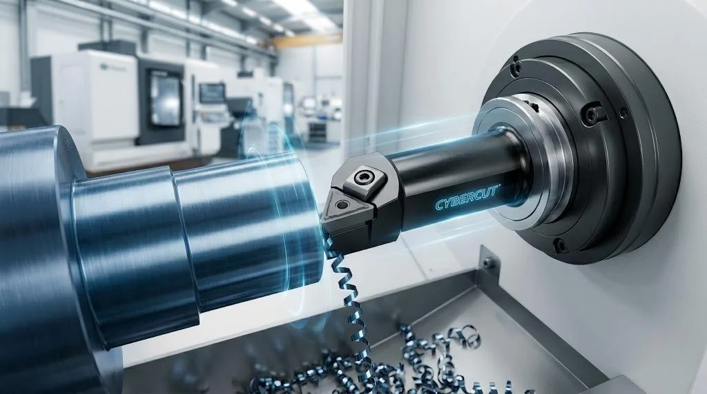
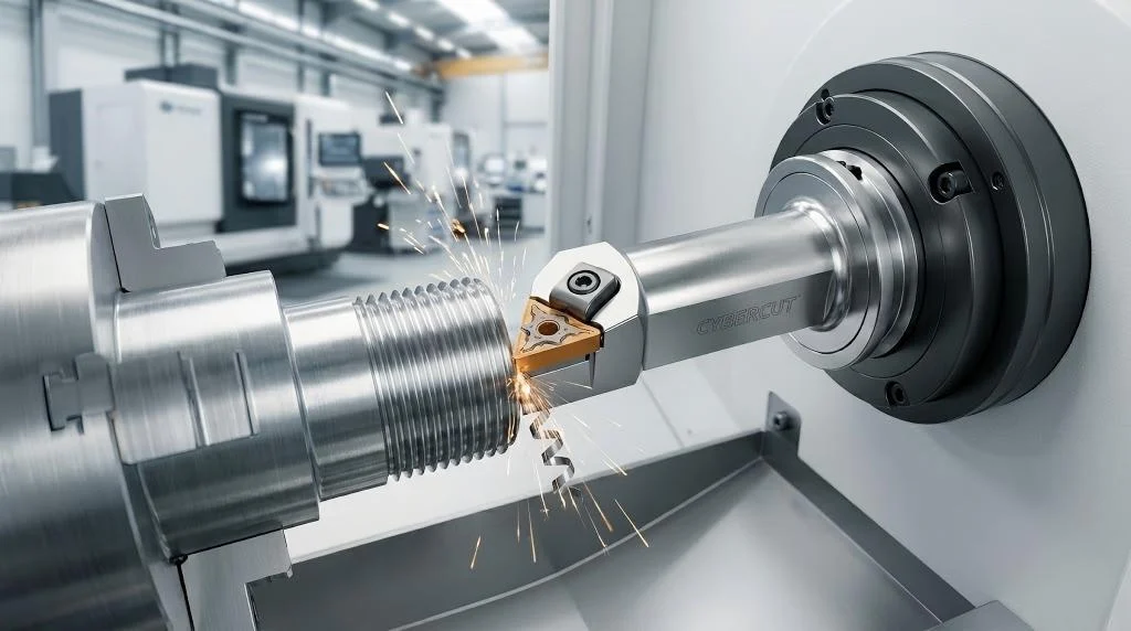
Unlike a twist drill, which is geometrically locked into producing a single specific diameter, indexable U drills offer profound operational versatility, especially on CNC lathes (turning centers). Because the cutting forces are distributed across two independent inserts, a CNC lathe programmer can offset the X-axis of the machine. By shifting the tool slightly off-center radially, the same 25mm U drill can be used to bore a hole to 26mm or 27mm. Furthermore, once the hole is drilled, the robust steel body and the outer insert can act as a boring bar to turn the internal diameter (ID) of the part, or even perform external turning and facing operations. This multi-functionality makes versatile CNC drilling tools an indispensable asset for maximizing turret space on complex mill-turn machines.
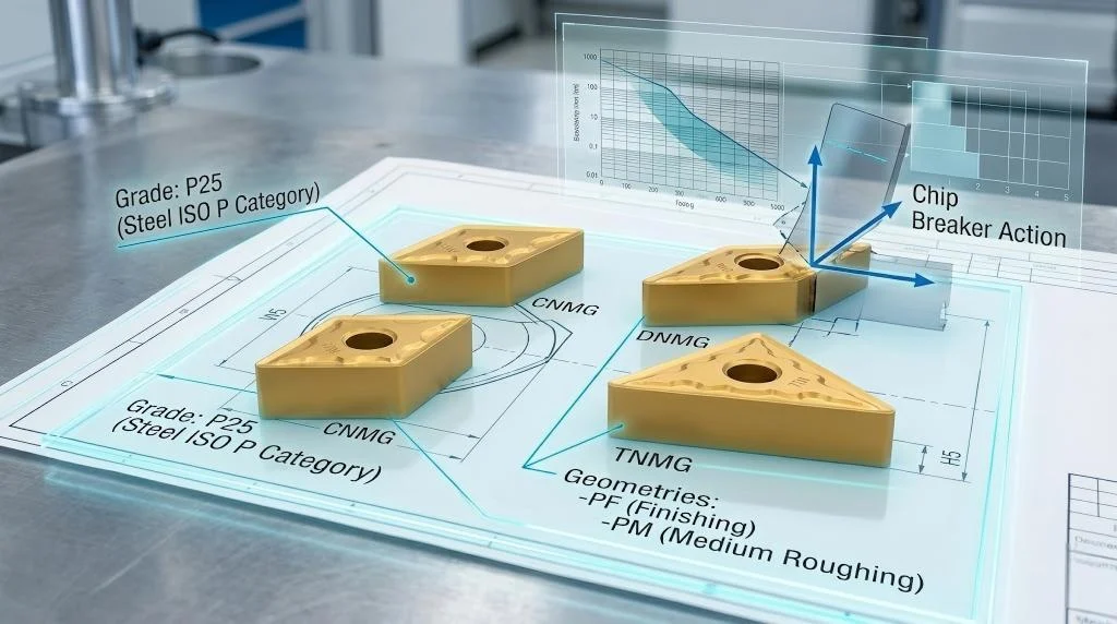
Selecting the Right Inner and Outer Inserts for Your U Drill
A critical engineering mistake made by novice machinists is assuming that the two inserts on a U drill perform the same function and endure the same tribological stresses. In reality, the cutting conditions at the center of the drill are vastly different from those at the periphery. Understanding this velocity gradient is the key to preventing premature failure in indexable U drills.
The Inner Insert: Surviving the Zero-Speed Zone
Cutting speed, or surface feet per minute (SFM / Vc), is calculated based on the diameter of the rotating tool or workpiece. At the outer diameter of a 30mm drill, the insert is traveling at maximum velocity. However, exactly at the center axis (0mm diameter), the theoretical cutting speed drops to absolute zero.
Because the speed is near zero at the center, the inner insert is subjected to immense compressive forces rather than high-speed shearing. The metal tends to tear and pressure-weld itself to the carbide, causing Built-Up Edge (BUE). To survive this harsh, slow-speed crushing environment, the inner insert must be manufactured from an extremely tough carbide grade (high cobalt content) and typically features a PVD coating to maintain a razor-sharp edge that resists BUE.
The Outer Insert: High-Speed Wear Resistance
The outer insert dictates the final diameter and surface finish of the hole. Operating at maximum cutting speed, it generates massive amounts of thermal energy. A tough, PVD-coated insert used here would quickly suffer from plastic deformation and crater wear due to the intense heat. Therefore, the outer insert requires a very hard carbide substrate (low cobalt content) protected by a thick CVD (Chemical Vapor Deposition) aluminum oxide coating. This CVD layer acts as a thermal barrier, allowing the insert to maintain its structural integrity during high-speed continuous cutting. When you source your indexable U drill inserts, you must specifically pair tough inner grades with hard outer grades to achieve optimal tool life.
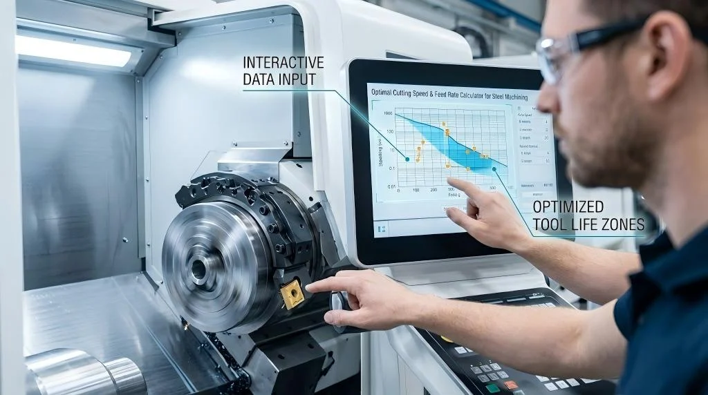
[Table] Machining Parameters: Speeds and Feeds for Common Materials using U Drills
Optimizing the cutting parameters for indexable U drills requires balancing the high-speed requirements of the outer insert with the low-speed limitations of the inner insert. The following table provides aggressive, high-efficiency starting parameters for standard ISO materials using properly matched carbide grades.
| ISO Material Group | Material Example | Hardness (HB) | Cutting Speed (Vc) m/min | Feed Rate (fn) mm/rev | Coolant Pressure |
| ISO P (Blue) | Unalloyed Carbon Steel (1045) | 125 – 200 | 180 – 250 | 0.08 – 0.15 | Minimum 15 Bar |
| ISO P (Blue) | Low-Alloy Steel (4140) | 250 – 320 | 140 – 200 | 0.08 – 0.12 | Minimum 20 Bar |
| ISO M (Yellow) | Austenitic Stainless (304) | 160 – 220 | 120 – 160 | 0.06 – 0.10 | Minimum 30 Bar |
| ISO K (Red) | Grey Cast Iron (GG25) | 180 – 250 | 200 – 280 | 0.10 – 0.18 | Dry or HP Air |
| ISO S (Brown) | Heat Resistant Alloys (Inconel) | 300 – 400 | 35 – 55 | 0.04 – 0.08 | Minimum 50 Bar |
*Note: Feed rates must be carefully scaled based on the diameter of the drill. A 15mm drill requires a much lighter feed per revolution than a 40mm drill to prevent core deflection.*
Dealing with Core Deflection and Vibration in 5xD Drilling
While indexable U drills are incredibly efficient at 2xD and 3xD (depth-to-diameter ratio) applications, pushing the tooling to 5xD, 6xD, or 7xD introduces severe mechanical challenges.
The Physics of Asymmetrical Cutting Forces
Because a U drill features only one cutting edge on the outer periphery and one on the inner, the radial cutting forces are not naturally balanced. This asymmetrical force constantly pushes the tool body sideways. In a short 2xD drill, the thick steel core easily resists this lateral pressure. However, in a long 5xD tool, the drill acts as a cantilevered beam. As the depth increases, the lateral forces cause the tool body to deflect radially, leading to severe vibration, poor hole straightness, and the rapid shattering of the outer carbide insert.
Advanced Strategies for Deep Hole Stability
To successfully deploy long-reach deep hole U drills, CNC programmers must manipulate the entry and exit parameters:
- Reduced Entry Feed: The drill is most vulnerable to deflection upon initial contact. Program the machine to enter at 50% of the normal feed rate for the first 2mm to 3mm of depth to establish a perfectly stabilized pilot bore.
- Addressing Interrupted Exits: When breaking through the back of a workpiece, the sudden release of cutting pressure causes violent lateral snapping. Reduce the feed rate by 50% approximately 1mm before breakthrough.
- Spindle Runout (TIR): Verify that the Total Indicator Reading (TIR) of your tool holder is as close to zero as possible. Even 0.05mm of runout at the spindle nose will magnify into massive geometric deviation at the tip of a 5xD drill.
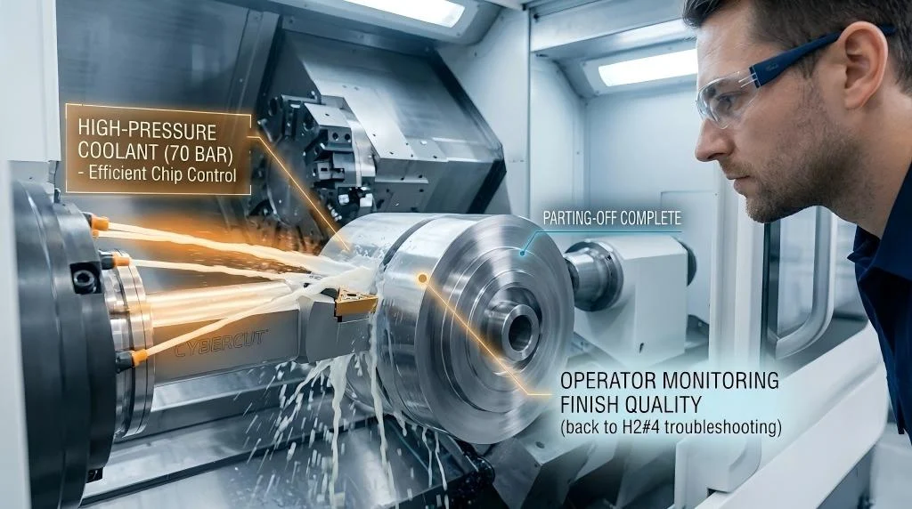
Coolant Requirements for Optimal Chip Evacuation
The primary cause of failure in deep hole machining is not edge wear; it is chip evacuation failure. If chips are not aggressively flushed out of the hole, they will pack into the flutes. The drill will recut these work-hardened chips, resulting in an immediate and catastrophic explosion of the tool body inside the workpiece.
To ensure the survival of your indexable U drills, the use of internal, Through-Spindle Coolant (TSC) is strictly mandatory. External flood coolant is entirely useless, as the rapidly spinning flutes and escaping chips act as a physical barrier.
High Pressure vs. High Volume
When setting up high-performance hole making tools, operators must understand the difference between coolant pressure and coolant volume.
- Volume (Flow Rate): Required to physically flush the mass of chips up the flutes and out of the hole. Larger diameter drills require massive volume.
- Pressure (Bar/PSI): Required to overcome the centrifugal force of the spinning tool, break through the vapor barrier generated by the boiling coolant, and force the fluid directly onto the cutting edge to prevent thermal shock.
Frequently Asked Questions (FAQ)
Q1: Do I need to drill a pilot hole before using indexable U drills?
A: Absolutely not. The asymmetrical overlapping geometry is engineered to shear across the center axis. Drilling a pilot hole is highly detrimental; if the inner insert falls into a pre-drilled void, it loses cutting resistance, causing the tool to violently vibrate and shatter.
Q2: What is the “core drop” or “disc” at the end of a through-hole?
A: Because the inner insert crosses the absolute center line by only a fraction of a millimeter, as the drill breaks through the back of the workpiece, a small, coin-shaped disc of uncut material falls away. Ensure your chip conveyors can safely handle these.
Q3: Can I use indexable U drills on a manual lathe or milling machine?
A: It is highly discouraged. These drills require massive horsepower, extreme rigidity, and high-pressure internal coolant. Manual machines lack structural rigidity, leading to severe chatter. For older setups, explore specific low-force drilling solutions.
Q4: Why did the steel body of my U drill melt and fuse inside the hole?
A: This is the textbook definition of a chip evacuation failure. Chips packed tightly at the bottom of the hole and jammed the drill body. The friction of the jammed tool generated enough heat to friction-weld the body to the workpiece.
Q5: Can I plunge mill or step-drill with these tools?
A: Yes. Due to their flat-bottom insert geometry and robust core, U drills are excellent for plunge milling overlapping holes to rapidly remove large volumes of material, provided the feed rate is carefully modulated.
Q6: How do I fix a hole that is drilling oversize?
A: If cutting oversize on a VMC, check spindle runout (TIR). On a CNC lathe, check the X-axis alignment of the turret. If the tool block is shifted off the true centerline, the drill will carve an oversized hole. Utilizing a high-quality eccentric sleeve from a dedicated drilling tool supplier can help dial in the exact center height.