In the sequence of CNC machining operations, threading is almost universally the final step performed on a workpiece. By the time a component reaches the threading cycle, it has already accrued significant value in terms of raw material costs and accumulated spindle time. Consequently, a failure during the threading pass—whether it is a torn thread flank, an incorrect pitch diameter, or catastrophic tool breakage—results in the immediate scrapping of an expensive, nearly finished part.
Unlike standard turning, where the tool geometry allows for relatively free chip flow, threading is a highly confined plunging operation. The tool must perfectly synchronize with the spindle’s rotation, carving a precise helical groove while absorbing immense, concentrated pressure on a microscopic cutting point. Mastering this operation requires moving beyond basic trial and error. It requires a deep engineering understanding of cutting kinematics, tribology, and tool wear mechanisms. By leveraging advanced diagnostics and upgrading your facility with premium CNC threading inserts, you can completely eliminate these costly bottlenecks. This comprehensive guide will dissect the mechanics of thread turning, detail the precise differences between wear patterns, and provide actionable, mathematical solutions to stabilize your threading operations.
Understanding the Mechanics of Thread Cutting

To properly troubleshoot wear, one must first understand the physics of the threading cut. Threading on a lathe is a multi-pass operation. The machine’s CNC controller synchronizes the rotational speed of the spindle (RPM) with the linear feed of the Z-axis to create a specific pitch or lead.
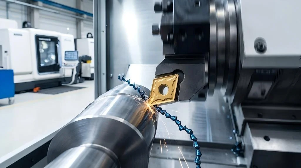
During a standard OD turning operation, the cutting edge is engaged on one primary face, and the chip shears away cleanly. In contrast, when a standard 60-degree or 55-degree threading insert engages the workpiece, it cuts simultaneously on three sides: the leading flank, the trailing flank, and the root radius.
This V-shaped engagement creates severe chip crowding. As the insert plunges deeper with each successive pass, the length of the cutting edge engaged in the material increases drastically. This geometric reality causes cutting pressure and thermal generation to spike exponentially toward the final passes. If the heat and pressure are not managed through optimized infeed strategies and high-quality carbide substrates found in a precision threading tools catalog, the fragile tip of the insert will rapidly deteriorate.
Flank Wear vs. Crater Wear: Identification and Solutions

Tool wear in threading is inevitable, but the type of wear is highly diagnostic. By examining the deteriorating edge of your CNC threading inserts under magnification, you can accurately deduce which machining parameter is actively destroying your tool.
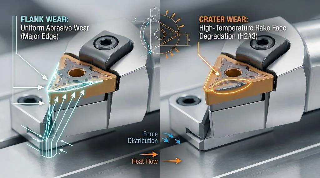
1. Flank Wear: The Abrasive Breakdown
Flank wear appears as a uniform band of abrasion on the clearance faces of the insert profile. It is a mechanical degradation caused by friction. If flank wear occurs rapidly, the cutting speed (Vc) is too high or the material is highly abrasive. Solution: Reduce the cutting speed by 15% to 20%. If cycle time cannot be sacrificed, upgrade your tooling setup by acquiring harder, more wear-resistant threading tool holders and inserts with a thicker CVD aluminum oxide coating.
2. Crater Wear: Thermal and Chemical Dissolution
Crater wear manifests as a distinct depression on the top rake face, caused by chemical diffusion between the steel chip and carbide substrate, catalyzed by extreme heat. As the crater grows deeper, it weakens the cutting edge until it snaps. Solution: Reduce the cutting speed immediately and ensure high-pressure coolant hits the rake face. If the problem persists in alloyed steels, source your specialized threading inserts with specific anti-diffusion CVD coatings designed for ISO P materials.
[Table] Diagnostic Chart for Threading Defects
When the thread profile itself fails inspection, the insert is usually the culprit. Use this diagnostic matrix to correlate the physical defect on your workpiece with the precise mechanical failure.
| Workpiece Defect | Visual Evidence | Primary Causes | Required Engineering Solutions |
| Torn or Ragged Flanks | Sides of the thread feel rough or fuzzy. | BUE due to low speed; incorrect shim angle. | 1. Increase cutting speed (Vc). 2. Verify helix angle and shim. |
| Vibration Marks (Chatter) | Visible chatter bands; high-pitched squeal. | Tool overhang too long; radial infeed forces; part lacks rigidity. | 1. Switch to modified flank infeed. 2. Reduce overhang. 3. Use tailstock. |
| Incorrect Thread Depth | Go/No-Go fails; shallow root. | Plastic deformation of tip; catastrophic tip breakage. | 1. Utilize constant-volume infeed. 2. Check center height alignment. |
| Work Hardened Surface | Insert squeaks on pass one; fails on pass two. | First pass depth of cut is too shallow (rubbing). | 1. Increase depth of cut on initial pass to penetrate scale. |
Choosing the Right Infeed Method (Radial vs. Flank Infeed)
The programming strategy used to plunge the insert into the workpiece is just as critical as the carbide grade itself. The CNC controller dictates how the tool approaches the final thread depth across multiple passes.
[Image comparing radial infeed, flank infeed, and alternating flank infeed methods for CNC threading]
1. Radial Infeed (Straight Plunge)
The tool plunges straight down the X-axis. The insert cuts simultaneously on both flanks, producing a stiff V-shaped chip that is difficult to evacuate. This should only be used for fine pitches (under 1.5mm) or highly abrasive materials where heat must be distributed equally.
2. Modified Flank Infeed (Angled Plunge)
The tool feeds at an angle slightly less than the thread profile angle (e.g., 29° for a 60° thread). The insert cuts almost entirely on one flank, generating a smooth spiral chip. Cutting forces are drastically reduced. This is the absolute best practice for the vast majority of CNC threading applications. To execute this perfectly, find the correct geometry in our threading category that matches your specific pitch requirements.
3. Alternating Flank Infeed
For extremely large pitches (Acme, Trapezoidal), the CNC program zig-zags the infeed, cutting on the left flank on pass one, right flank on pass two, etc. This balances wear perfectly on both sides of the tool.
Selecting the Correct Shim for Proper Tool Angle
Perhaps the most universally misunderstood element of lathe threading is the application of the anvil or shim. A threaded component is a helix wrapped around a cylinder. Therefore, the thread groove sits at a specific angle, known as the helix angle (λ).
[Image showing the relationship between thread helix angle and insert shim inclination angle]
If a standard threading insert is mounted perfectly flat (0° inclination) and fed into a steep helix, the leading flank will rub aggressively against the workpiece, while the trailing flank will have excessive clearance, causing torn threads and chatter.
Calculating the Helix Angle
To ensure equal clearance, the insert must be tilted to match the helix angle using a precision angled shim. The mathematical formula is: tan(λ) = Pitch / (π * Effective Diameter).
Most standard holders come with a 1.5° or 1° positive shim for standard metric/UN threads. If cutting multi-start threads, coarse pitches on small diameters, or left-hand threads, you must calculate the angle and swap the shim accordingly. Utilizing advanced lathe threading inserts requires strict adherence to these geometric laws.
Frequently Asked Questions (FAQ)
Q1: What is the difference between partial profile and full profile CNC threading inserts?
A: Partial profile inserts feature a sharp V-shape allowing one insert to cut multiple pitches, but they do not radius the thread crest. Full profile inserts are precision-ground for one specific pitch, machining the root, flanks, and crest simultaneously for a perfect, standard-compliant profile.
Q2: How do I stop chatter when cutting long, slender threaded shafts?
A: Use a live center in the tailstock to support the part. Switch your CNC program to use a modified flank infeed (e.g., 29 degrees), and select a threading insert with a sharp, positive PVD geometry to lower radial cutting forces.
Q3: Should I run coolant when threading, or cut dry?
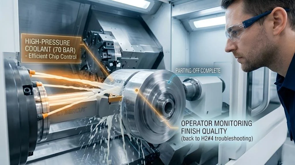
A: Threading should almost always be performed with high-pressure coolant. The low surface speeds near the thread root invite severe Built-Up Edge (BUE). Coolant provides critical lubricity to prevent material welding and flushes chips.
Q4: What is the difference between thread turning and thread milling?
A: Thread turning is performed on a lathe using a single-point insert. Thread milling is performed on a milling center (VMC) using a rotating, multi-flute tool. Thread milling is superior for asymmetrical parts, blind holes, or exotic alloys where a broken tap would scrap the part.
Q5: How do I set up my tool for cutting a left-hand thread?
A: Start the tool at the chuck end and feed the Z-axis away from the spindle. Crucially, change the shim beneath the insert to a negative inclination to match the reversed helix angle, or rely on robust CNC thread making tools designed for left-hand applications.
Q6: How many passes should I program for a specific thread pitch?
A: As a general rule, a 1.0mm pitch requires 4-5 passes, 2.0mm requires 6-8 passes, and 3.0mm requires 10-12 passes. Always utilize a “constant volume” infeed strategy (like G76) which reduces the depth of cut on each successive pass to keep cutting pressure constant.